Payload Development Standards
To ensure the safety of the UAV during flight missions with payload devices, please follow the relavant development standards of Autel Robotics when using the PSDK to develop payload devices.
Hardware Interface Standards
Notes:
- Do not short-circuit the pins of the UAV or hardware platform.
- Do not connect the UAV to a power output system or input current to the UAV.
- The payload capacitor must be ≤500 uF. If it exceeds this threshold, the UAV will trigger a short-circuit protection during the power-on moment, and the SDK power output will be turned off.
- The protection current is 4 A (3 A for P-Port Lite). If the current limit is exceeded, the UAV will cut off the power within 5 ms to ensure flight safety.
- The P-Port Lite interface is only supported by the EVO Max series multirotor UAVs.
| Interface Name | Interface Function | Requirements |
| P-Port Interface | Power Output | EVO Max Series Rated Voltage: 12.8–17 V Rated Current: 4 A |
| EVO Max Series Rated Voltage: 19.8–27.6 V Rated Current: 4 A | ||
| PPSI Pin Voltage | 3.3 V | |
| UART Pins | Must follow the 3.3 V TTL standard (1.8 V TTL standard for EVO Max series). | |
| P-Port Lite Interface | USB Interface | Must follow USB 2.0 protocol |
| Power Output | EVO Max Series Rated Voltage: 12.8–17 V Rated Current: 3 A | |
| USB Interface | Must follow USB 2.0 protocol | |
| Power Output | Rated Voltage: 12 V Rated Current: 4 A | |
| C-Port Interface (Gimbal Adapter Interface) | PPSI Pin Voltage | 3.3 V |
| UART Pins | Must follow 3.3 V TTL protocol | |
| CAN Pins | Must follow CAN2.0B protocol |
Interference Compatibility Requirements
| Interference Type | Compatibility Requirements |
| Light Flicker | The light flicker frequency must not be in the range of 0.5–50 Hz |
| Light Wave Emission | - The light source should ideally be around 5000 K (white light) or near infrared - Single red, green, or blue light is prohibited |
| Magnetic Field | - Strong magnetic substances should not be carried by load devices, magnetic heading interference < 0.5 uT - High-intensity alternating magnetic fields should be avoided |
| Electromagnetic Noise | Avoid frequency bands: 0.8–1.5 GHz, 2.2–2.7 GHz, 4.8–6.0 GHz - Equivalent isotropic radiated power (EIRP) must be less than 1 W |
| Acoustic Noise | Avoid frequency band: 2.5–4 KHz |
Structural Design Standards
Notes:
- To avoid damage to both the UAV and the payload device caused by the UAV's flight inertia, such as collision with the battery compartment and propellers, please design the payload device's size reasonably.
- To minimize the impact of the payload on the UAV’s moment of inertia, please reduce the payload’s size as much as possible.
General Structural Standards
Notes:
- For more detailed and accurate data, please refer to the user manual for the corresponding UAV model. The user manual can be downloaded from the Autel Robotics official website for the respective model.
| Structural Parameter | EVO Max Series | Autel Alpha |
| 3D Model File | Contact the SDK Technical Support Team for access | |
| Structural Interference | During flight missions, the payload device must not collide with the UAV's components: arms, propellers, or gimbals, and must not obstruct the field of view (FOV) of the visual and radar systems. | |
| Vibration | After the UAV powers on, the payload device must not cause vibrations that affect the IMU while the UAV is stationary, ensuring normal initialization and takeoff. | |
| Shell Temperature | -30 ℃ to +70 ℃ | |
| Payload Capacity | Maximum Payload Capacity: <200 g | Maximum Payload Capacity < 2000 g (with dual batteries installed) |
| Height | The height of the PSDK payload must not exceed 70 mm above the mounting hole. | No Limitation |
| Motion Path | The motion path of the payload device must not obstruct sensors: 1. Front stereo vision system FOV: 67° × 85° (horizontal × vertical), perceivable range <30 m 2. Rear stereo vision system FOV: 67° × 85° (horizontal × vertical), perceivable range <25 m 3. Upward stereo vision system FOV: 120° × 185° (horizontal × vertical), perceivable range <30 m 4. Downward stereo vision system FOV: 120° × 185° (horizontal × vertical), perceivable range <35 m 5. Front and rear millimeter-wave radar detection range: ±60° × ±30° (horizontal × vertical), perceivable range 0.3–50 m 6. Upward millimeter-wave radar detection range: ±60° × ±30° (horizontal × vertical), perceivable range 0.3–20 m 7. Downward millimeter-wave radar detection range: ±60° × ±30° (horizontal × vertical), perceivable range 0.15–80 m | The motion path of the payload device must not obstruct sensors and vent holes: 1. Front stereo vision sensor FOV: 120° × 130° (horizontal × vertical), perceivable range <30 m 2. Rear stereo vision sensor FOV: 120° × 130° (horizontal × vertical), perceivable range <26 m 3. Downward stereo vision sensor FOV: 120° × 130° (front-rear × left-right), perceivable range <43 m 4. Left-right stereo vision sensor FOV: 120° × 130° (horizontal × vertical), perceivable range <45 m 5. Front-rear and left-right millimeter-wave radar detection range: ±35° × ±30° (horizontal × vertical), perceivable range 0.3–30 m 6. Upward millimeter-wave radar detection range: ±35° × ±30° (horizontal × vertical), perceivable range 0.3–20 m 7. Downward millimeter-wave radar detection range: ±35° × ±30° (horizontal × vertical), perceivable range 0.15–40 m |
| Center of Gravity | Mount the payload device using the body's mounting holes; the payload's center of gravity must lie between the front and rear mounting holes, with the overall UAV's center of gravity remaining within 1 cm of the midpoint of the rear mounting hole. If the center of gravity shifts forward, it must be <2 mm; if the center of gravity shifts backward, it must be <8 mm. | Secure the payload device using the lower bracket beneath the parachute module. The payload's center of gravity must align with the center of the parachute module, and the overall UAV's center of gravity must remain within 15 mm in the fore-aft direction. |
Structural Standards for Gimbal Adapter Ring
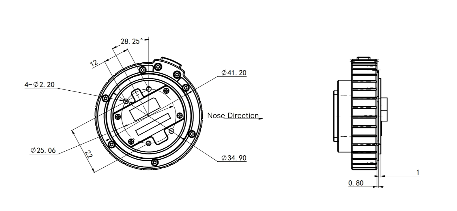
- Distance from the adapter ring's mounting center to the outermost edge of the payload: <48 mm
- Total payload height: <155 mm; total width: <120 mm
- Payload weight mounted via adapter ring: <1000 g
Custom Data Transmission Standards
| Channel Type | Transmission Direction | Rate Limitation |
| Command Channel | Mobile App -> Payload Device | ≤2048 B/s |
| Payload Device -> Mobile App | ||
| Cloud (e.g., cloud API) -> Payload Device* | ||
| Payload Device* -> Cloud (e.g., cloud API) | ||
| High-Speed Data Transmission Channel | Payload Device -> Mobile App | ≤4 Mbps |
Tip:
- The connection between the cloud (e.g., cloud API) and the payload will be supported once the interconnection functionality is available in future updates.
Video Stream Transmission Standards
When developing camera-related payload devices with PSDK, the following H.264 encoding standard must be selected.
Features
- A widely used and easily accessible H264 stream format.
- Stream sent in this video format will be transparently transmitted through the UAV to the App for decoding, with real-time bitrates not exceeding the feedback value.
- SEI content in this format can be transmitted to the App.
Requirement For camera-related payload devices developed with PSDK using the H.264 standard, the following key configuration information must be considered:
| Key Frame | H.264 Standard Item | Value |
| Video Resolution | - | Maximum 1280 × 720 |
| Frame Rate | - | Maximum 30 fps |
| Bitrate | - | Maximum 8 Mbps |
| Recommended Aspect Ratio | - | 4 : 3 |
| GOP Encoding Structure | - | - |
| Level Number | Level Number | <5.1 |
| profile_idc | 7.3.2.1.1 | Baseline=66, Main=77, High=100 |
| YUV420 Format | 7.3.2.1.1 | chroma_format_idc=1 |
| 8Bit Video | 7.3.2.1.1 | bit_depth_luma_minus8=0 bit_depth_chroma_minus8=0 |
| Encoder Custom Scaling Matrix Not Allowed | 7.3.2.1.1 7.3.2.2 | seq_scaling_matrix_present_flag=0pic_scaling_matrix_present_flag=0 |
| Frame Format Only, Field Encoding Not Supported | 7.3.2.1.1 | frames_mbs_only_flag=1 |
| Only P-Frames and I-Frames Allowed, with Single Reference Frame for P-Frames | 7.3.3 7.3.2.2 7.3.3 | slice_type=0 or 2 num_ref_idx_l0_default_active_minus1=0 num_ref_idx_active_override_flag=0 |
| Multi-Slice Group Not Supported | 7.3.2.2 | num_slice_groups_minus1=0 |
Notes:
- When using the H.264 encoding standard, the GOP encoding structure must use Period I (Intra-coded frames, with an IDR frame inserted every 1 second to ensure image data can be recovered if lost).