Debug Tools Tutorial
To help developers quickly debug drone functions, Autel provides Debug Tools, which can debug interfaces such as parameter access and behavior control of drone hardware modules.
Start Debug Tools(SDK Demo) and enter the main interface, as shown below:
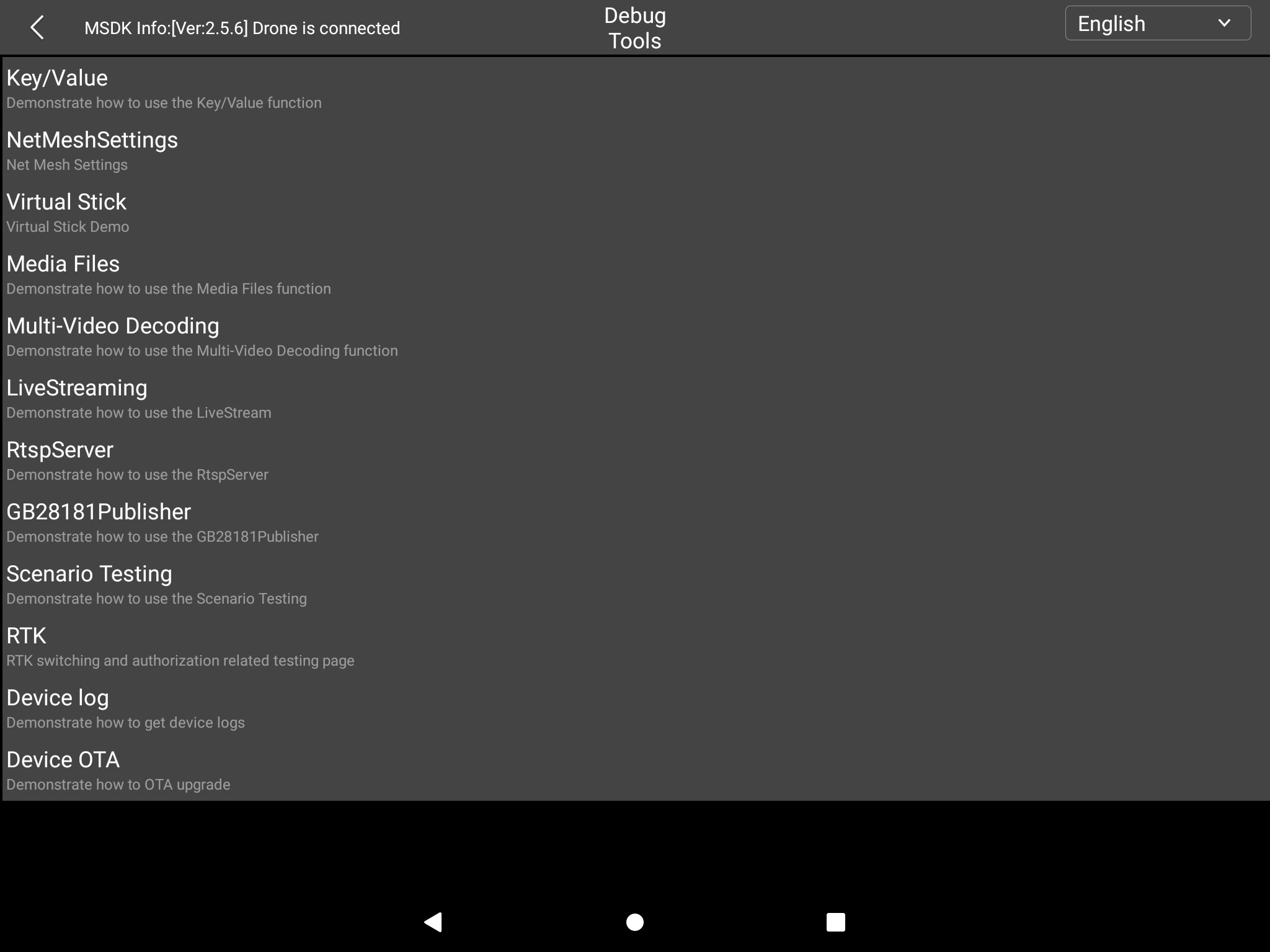
Debug Tools mainly includes the following parts:
- Key/Value:debugs all keys supported by drone
- NetMeshSettings: Network-Mesh processes, interface call demonstration
- Virtual Stick:Demonstrate how to use the virtual stick
- Media Files: uploads, downloads, queries, and deletes mission files; obtains, deletes, and downloads video files; performs health checks
- Multi-Video Decoding:Decoding: decodes videos in different formats at the same time
- LiveStreaming:Demonstrate how to use RTMP for streaming
- RtspServer:Demonstrate how to use RTSP for streaming
- GB28181 Publisher:Demonstrate how to use GB28181 protocol for streaming
- Scenario Testing:Test remote control pairing; remote control calibration, compass calibration, gimbal calibration; photo, video recording and other scene tests
- RTK:RTM switching and authorization related test pages
- Device log:Demonstrate how to get device logs
- Device OTA:Demonstrate how to perform OTA upgrade on the device
Key/Value
Overview
The KeyManager class provides a set of methods to access the parameters of the hardware module and control the behavior of the hardware module. Create an AutelKey instance through the createKey method provided by the KeyTools class. Then initiate the Set, Get, Action, Listen or Report of the Key through the KeyManager to complete the control of the drone hardware module.
Through the Key/Value debugging module, the parameters and behaviors of the drone hardware module can be quickly set and read.
Interface Description
Enter the Key/Value page, as shown below:
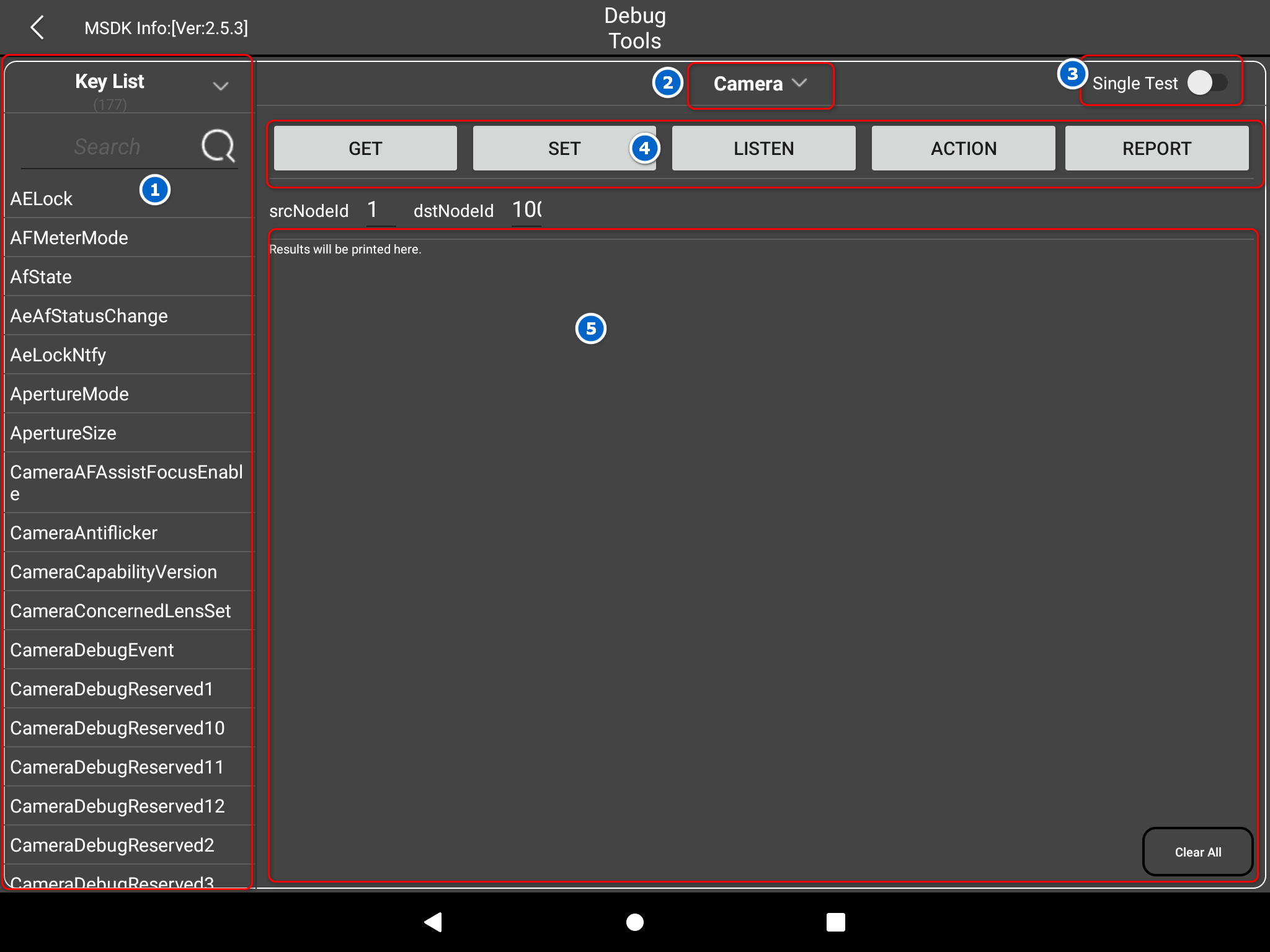
On the left of the page is the Key List, which displays a list of all the keys supported by the currently selected module (the default module is the camera module). You can search by turning pages or searching directly.
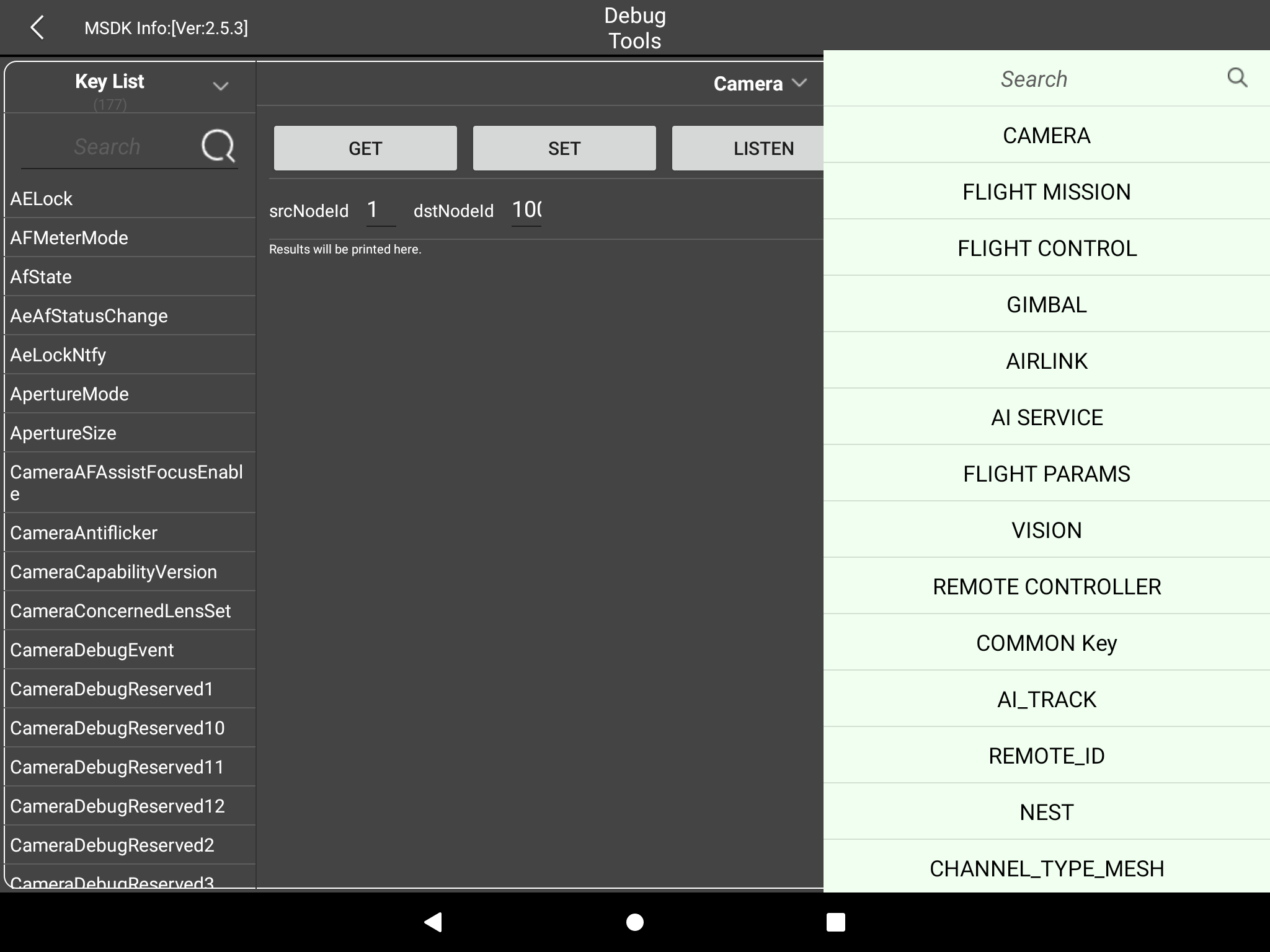
Camera is the currently selected debugging module. You can click it to switch to other modules.
Single Test Switch between single test and batch test mode. To switch to batch test, click ④ to execute all the Key/Value tests in the left list.
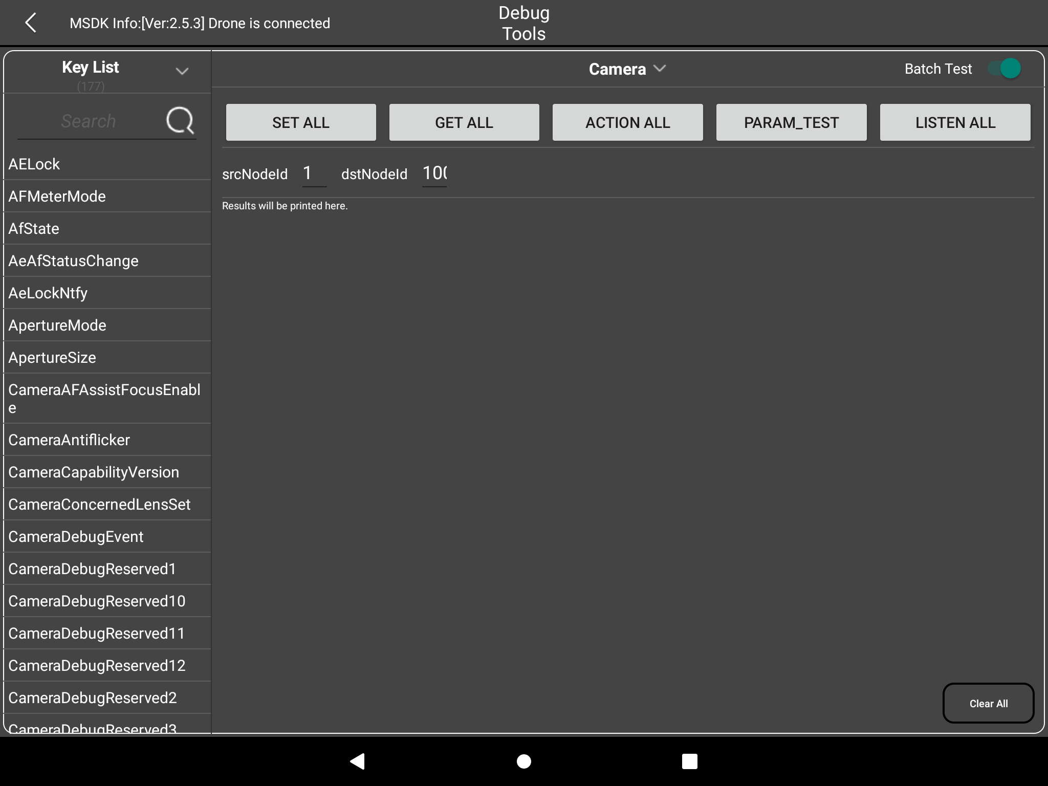
Represents the operation of each Key. GET/SET is for getting and setting Key values. LISTEN can monitor changes in Key values. ACTION can perform an action, such as taking a photo. REPORT represents reporting information through the Key.
The middle part is the log of the operation process and the result output window. The Clear All button in the lower right corner can clear the displayed log.
Test Description
Get Method
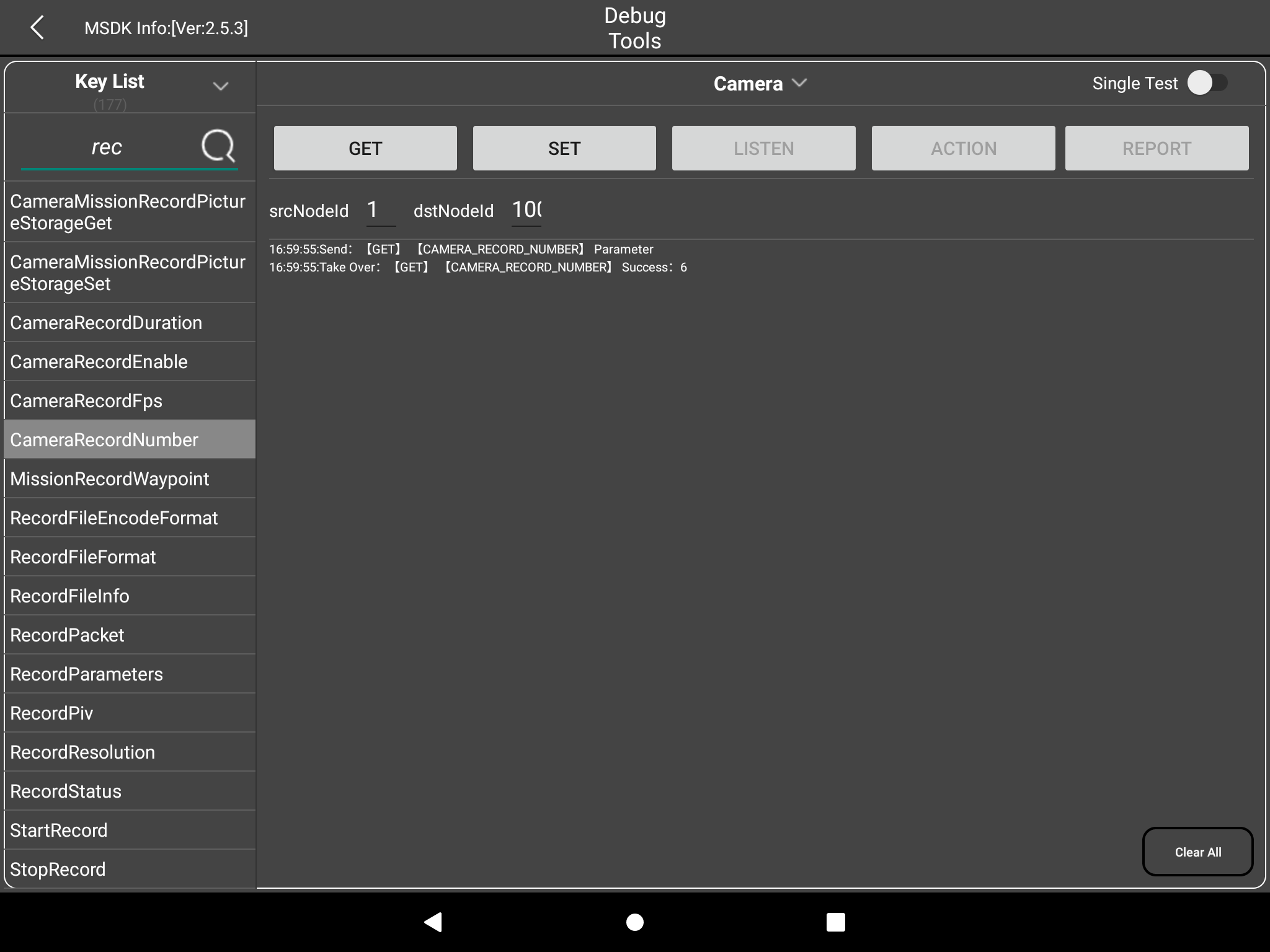
For example: To obtain the number of saved videos, search and select the number of saved visual camera videos in the Key List. Since CameraRecordNumber only supports GET and SET, the LISTEN, ACTION, and REPORT buttons on the right will be grayed out and cannot be clicked. Click the GET button, and the CameraRecordNumber parameter print will be displayed below.
The following figure is a screenshot of the print result after the Get method is successfully called:

Set Method
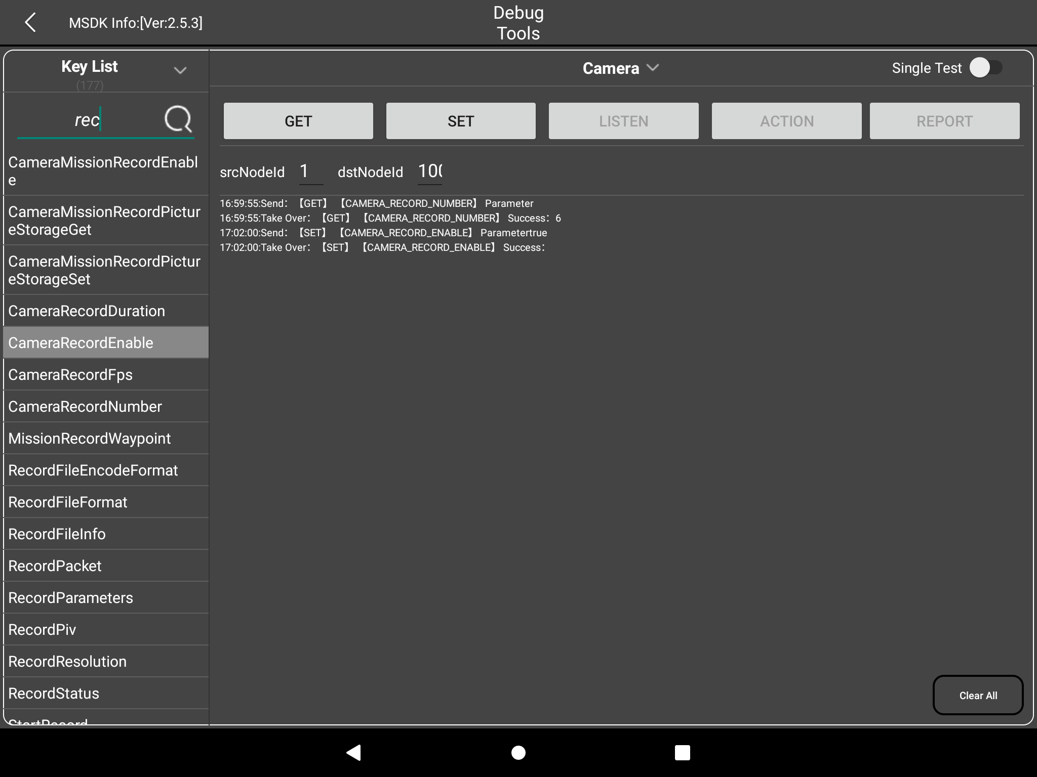
For example, to set the recording switch, search and select CameraRecordEnable in the Key List. Since CameraRecordEnable only supports GET and SET, the LISTEN, ACTION, and REPORT on the right will be grayed out and cannot be clicked. Click the SET button to set the parameters. The print result of the success or failure of the CameraRecordEnable request will be displayed below.
Set method input window:
Execution results display:
Listen Method
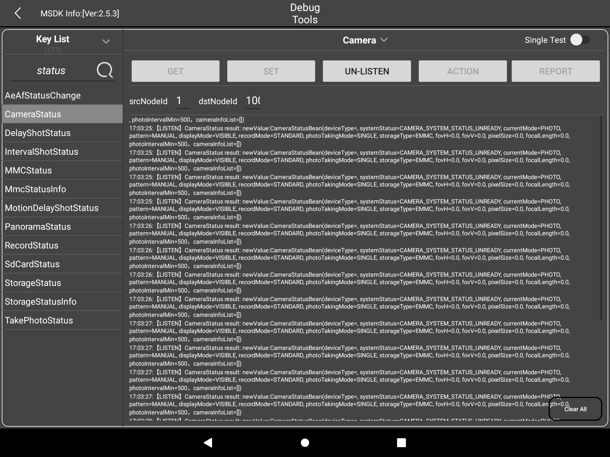
For example: to get the camera status, find and select CameraStatus in the Key List. Since CameraStatus only supports listening, the GET, SET, ACTION, and REPORT on the right will be grayed out and cannot be clicked. Click the LISTEN button, and the parameters of CameraStatus will be printed below. At the same time, the LISTEN button will become UnListen. Click UN-LISTEN to cancel listening and stop parameter printing.
The following figure is a screenshot of the print data after LISTEN is successful:
Action Method
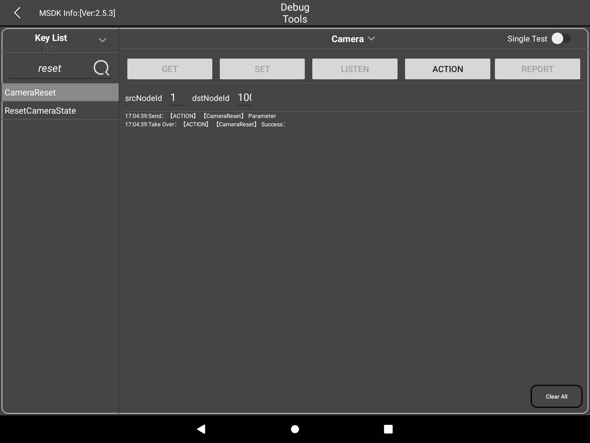
For example: To reset the camera, search and select CameraReset in the Key List. Since CameraReset only supports ACTION, the GET, SET, LISTEN, and REPORT buttons on the right will be grayed out and cannot be clicked. Click the ACTION button, and the print result of the success or failure of the CameraReset request will be displayed below.
The following figure shows a screenshot of the print result after calling CameraReset successfully.:
Report Method
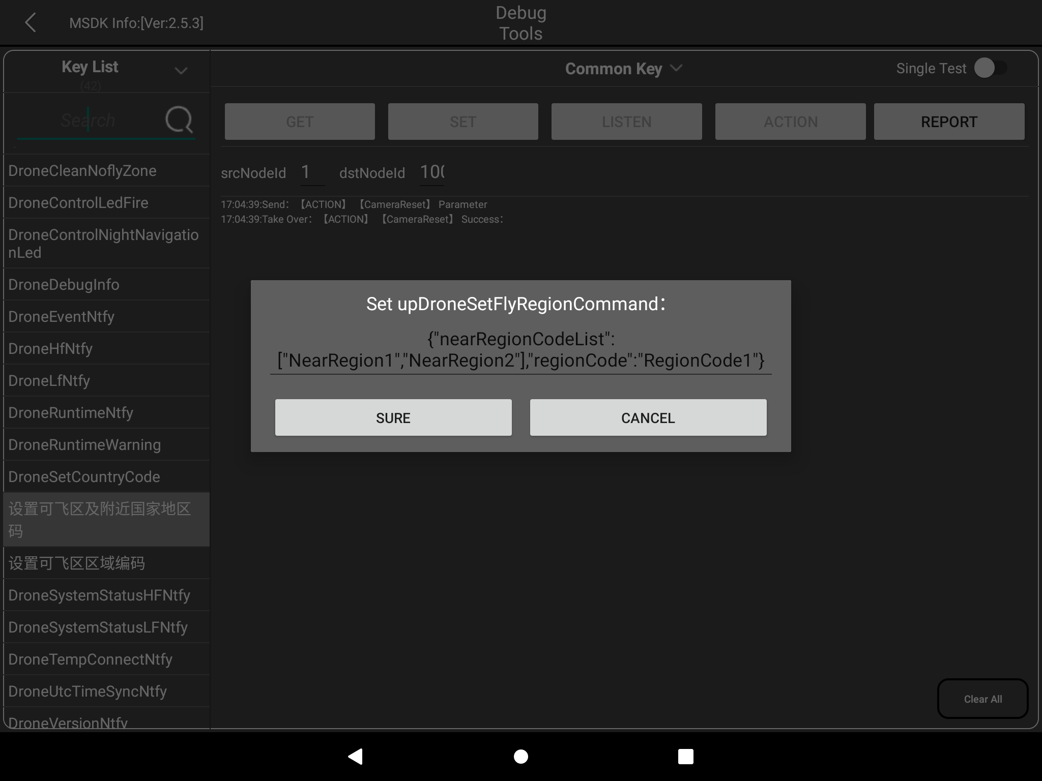
The REPORT method is not commonly used and is mainly used to report messages, such as setting the flyable zone and nearby country codes in General Parameters, as shown in the following figure:
The Key test methods for other modules are the same as above.
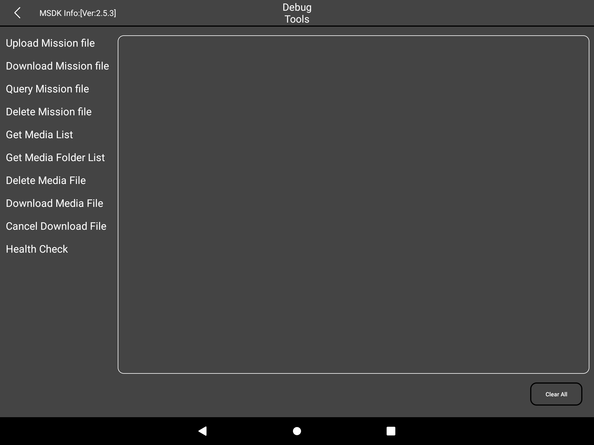
Media Files
Enter the Media Files page, you can see that this function supports the management test of task files and media files
 The functions of multimedia files are demonstrated below. The functions of task files are similar.
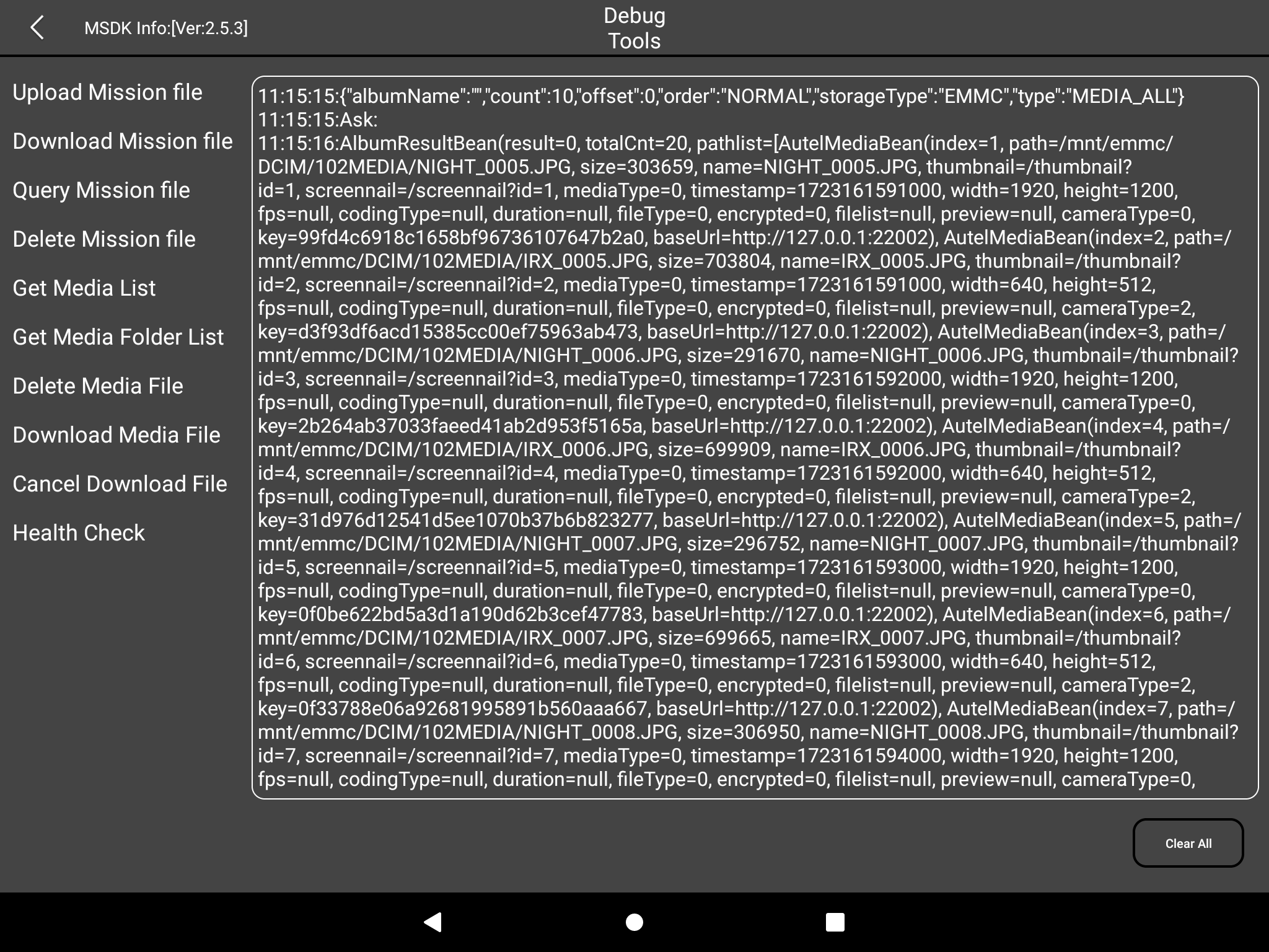
Get Media List: Query the media file list, and input parameters as shown below
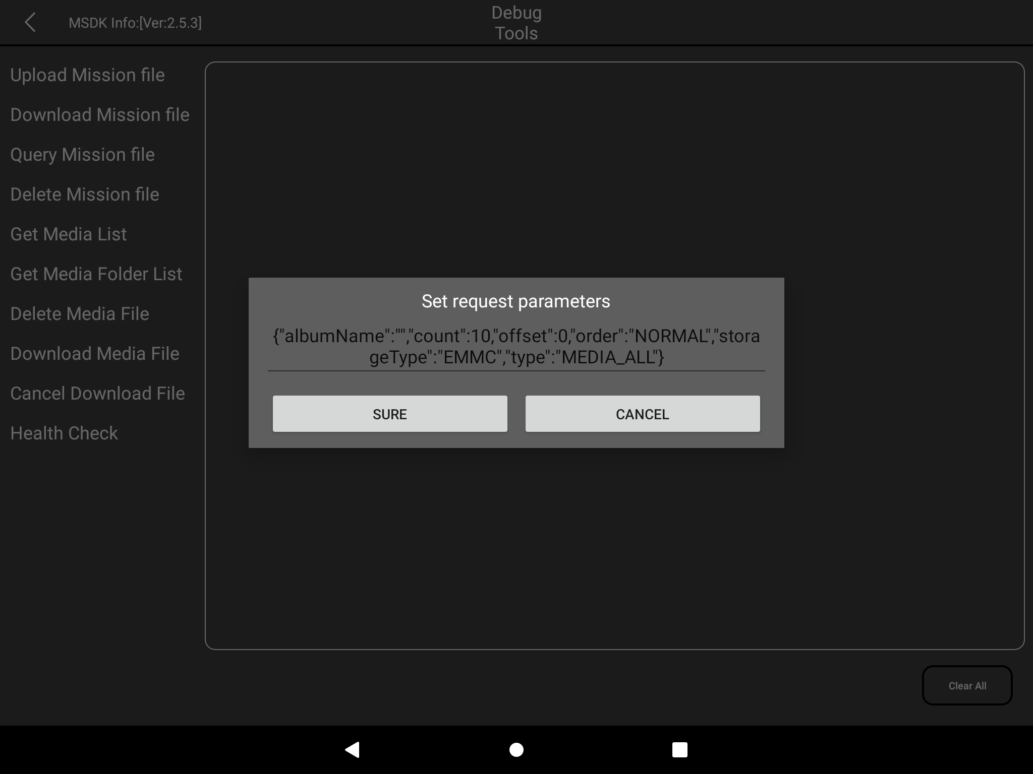
count:How many files need to be queried offset:Start position storageType: Storage type, EMMC - Flash memory; SD - SD card orderType: Sorting method, NORMAL - sequential; REVERSE - reverse type: 文件File type, MEDIA_ALL - all files; MEDIA_VIDEO - video files; MEDIA-PHOTO - picture files
The query results are as follows:
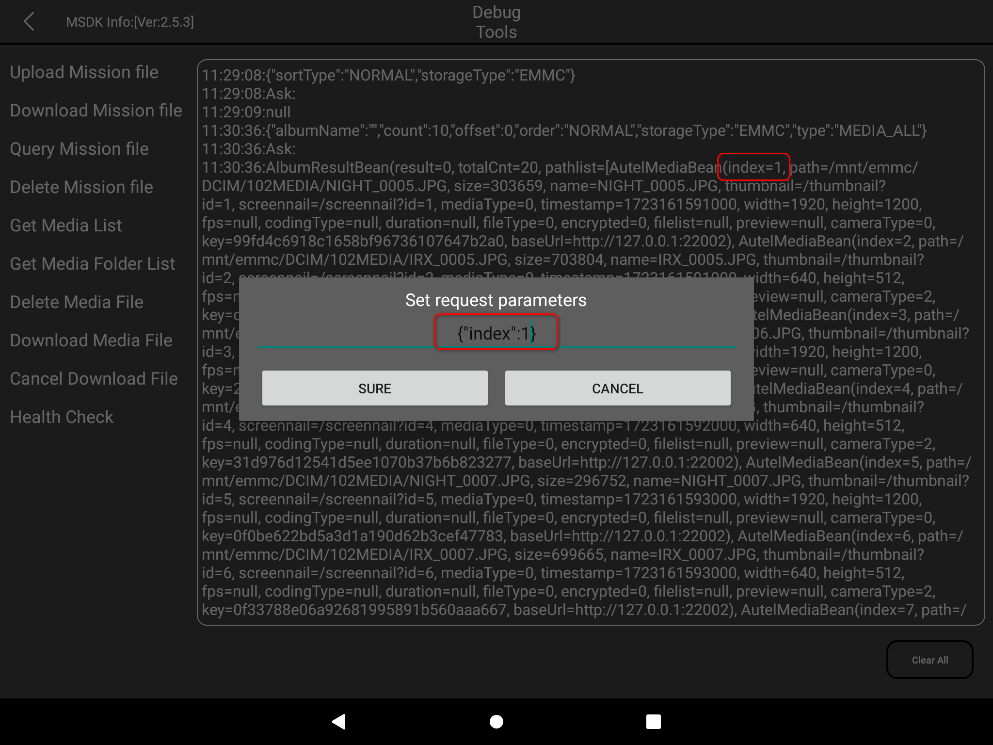
- Delete Media File: Delete video or image files
index: The index of the previous query results
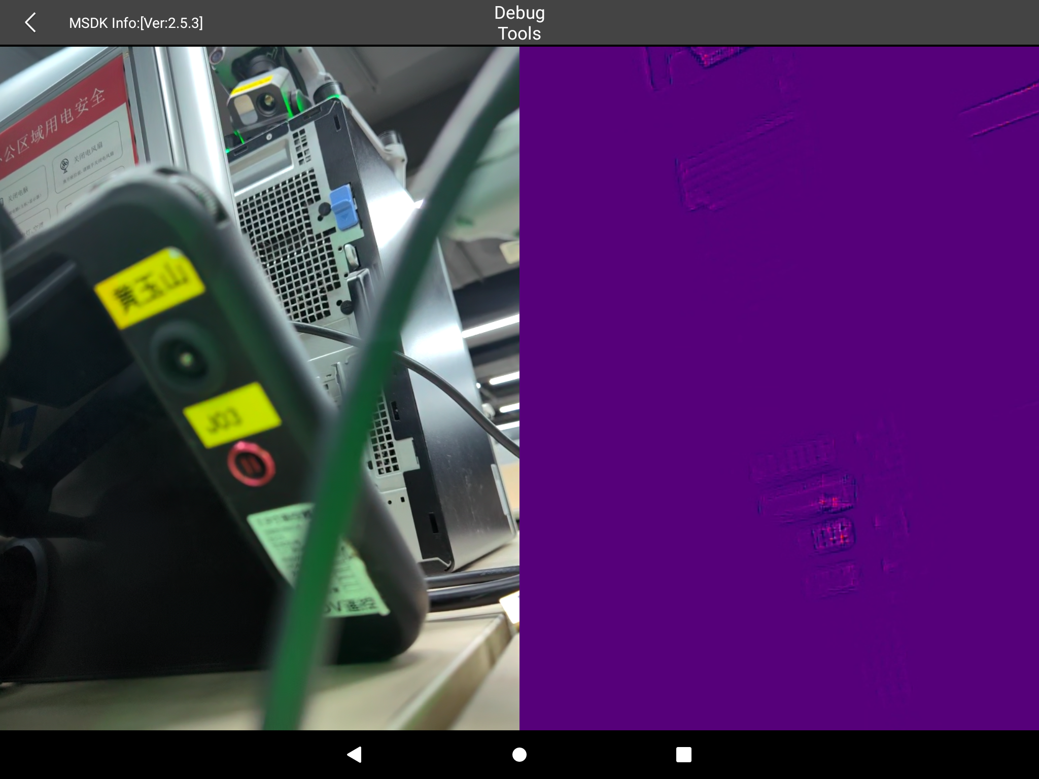
Multi-Video Decoding
This module is mainly used to test whether the zoom/infrared camera is normal. Click the Multi-Video Decoding item to enter the interface, as shown in the figure below. If the zoom and infrared videos can be displayed normally, it means it is normal.
LiveStreaming
The LiveStreaming item is mainly used to test the RTMP streaming function:
- Enter the LiveStreaming page and check whether the video is normal.
- Fill in the RTMP streaming address, and then click the START button to start streaming, as shown below:
Note: This function requires you to build an RTMP server yourself. After pushing the stream, you can view the video stream on the RTMP server.
RtspServer
RtspServer is similar to LiveStreaming, and is mainly used to test the RTSP streaming function:
- Enter the RtspServer page and check whether the video is normal.
- Fill in the RTSP push stream address, and then click the START button to start pushing the stream, as shown in the figure below:
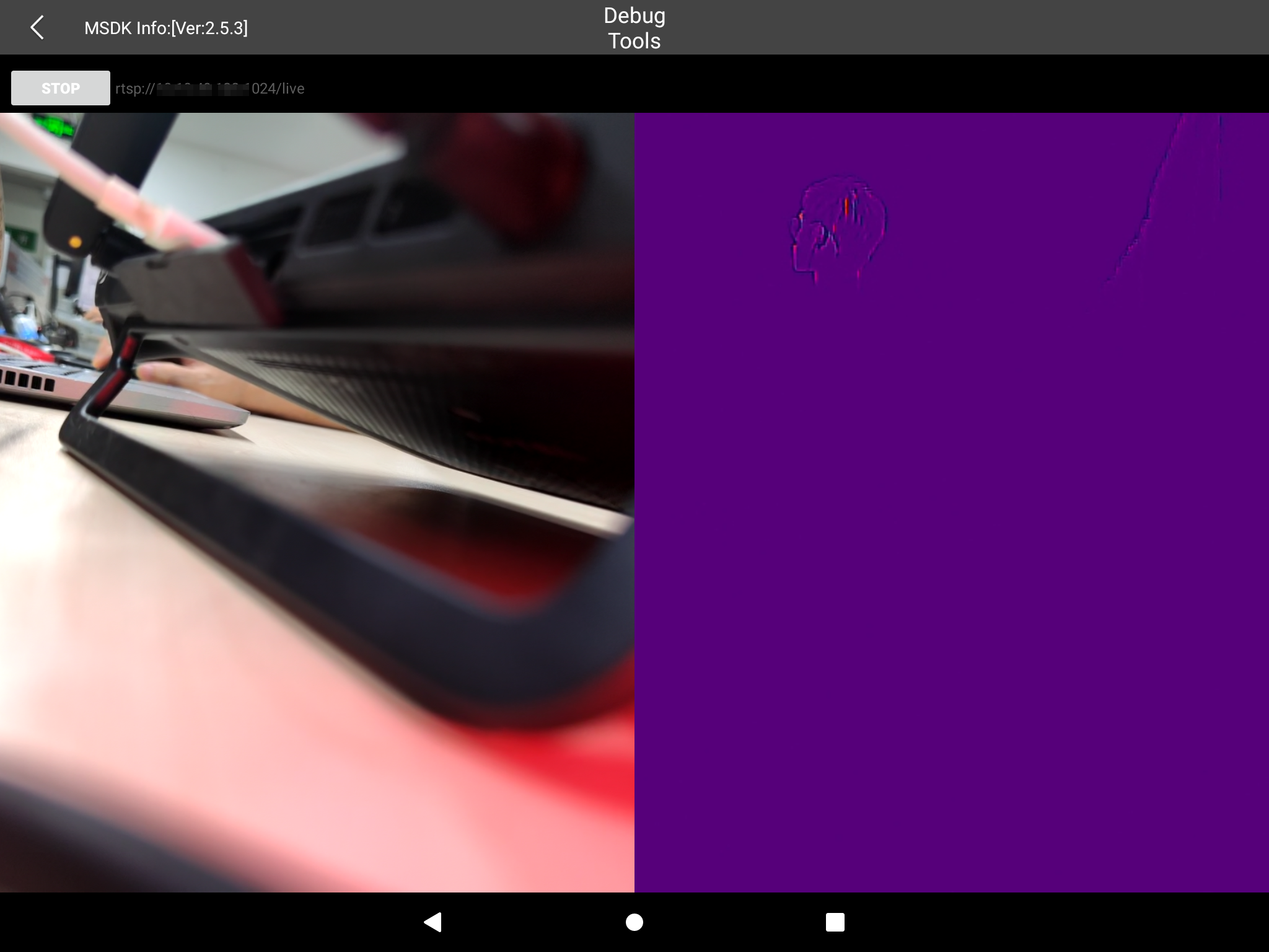
Note: This function requires you to build an RTSP server yourself. After pushing the stream, you can view the video stream on the RTSP server.
Scenario Testing
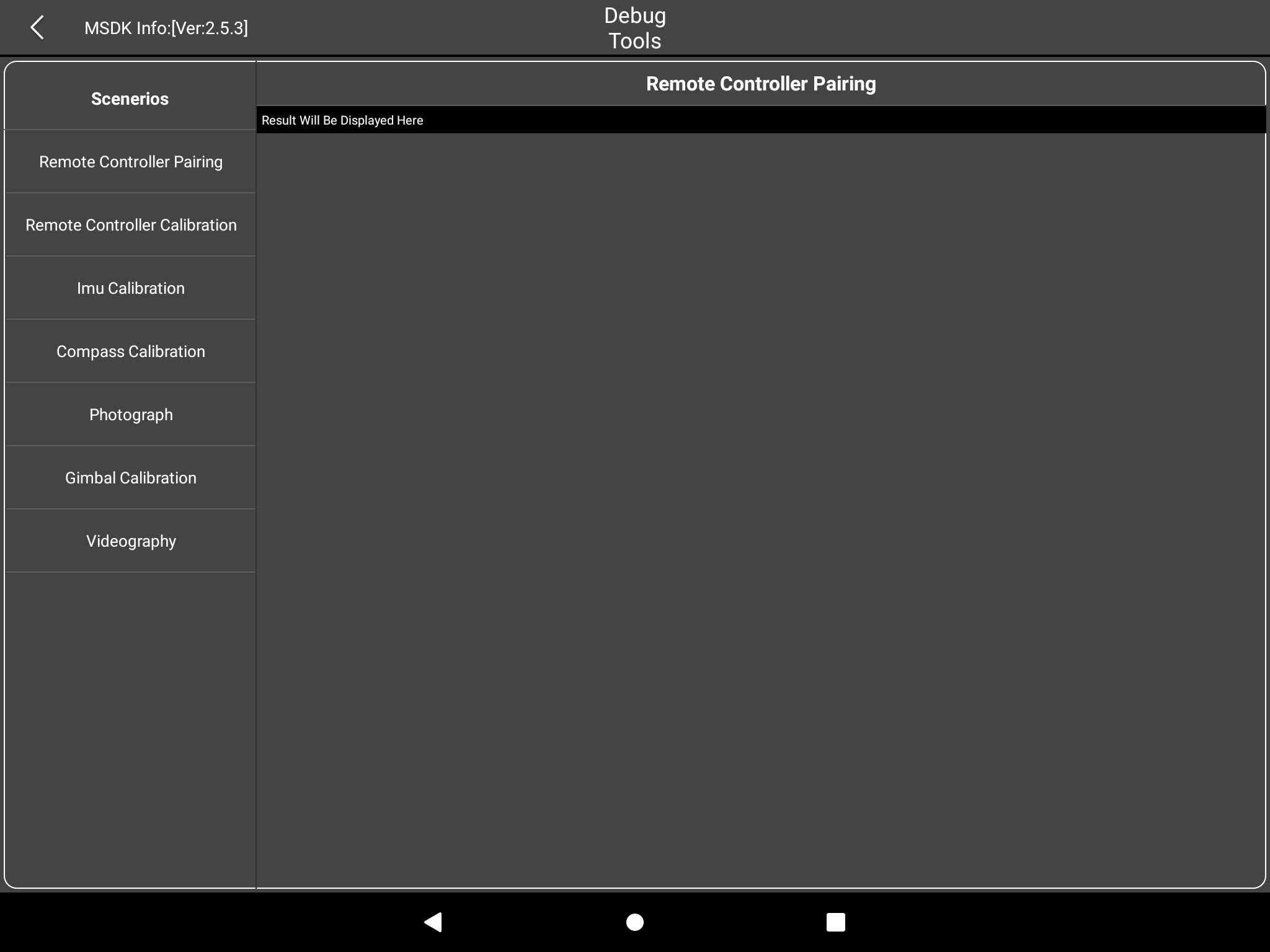
Scenario Testing is a test for certain specific functions and scenarios. The included test scenarios are shown in the following figure:
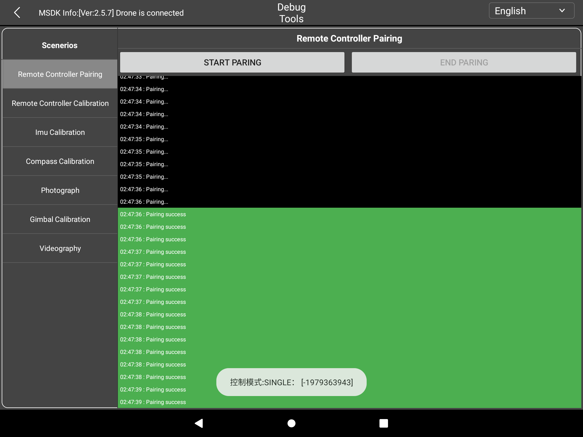
Remote Controller Pairing: Test pairing the remote controller with the drone Click START PAIRING to start pairing, and then click on the green "Pairing Success" to indicate that the pairing is successful.
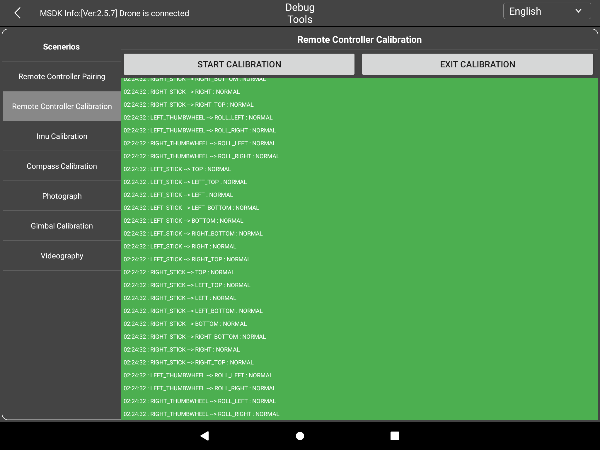
Remote Controller Calibration Click START CALIBRATION to start calibration. The remote control will emit rapid beeps. Move the left and right joysticks to eight directions: up, down, left, right, lower left, lower right, upper right, and upper left. Keep the movement for more than 1 second until a beep sounds. This means that the calibration is complete in this direction. Similarly, move the left and right rollers to the full position in each direction until a beep sounds. This completes the calibration in this direction. After all directions are calibrated, the calibration process ends automatically.
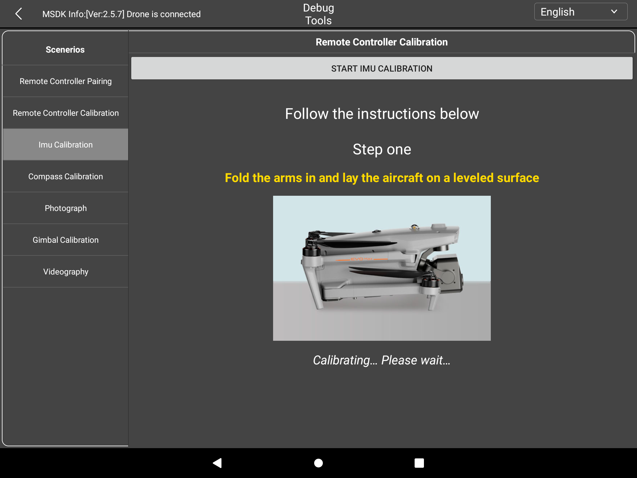
IMU Calibration: Click START IMU CALIBRATION and follow the instructions to calibrate the IMU.
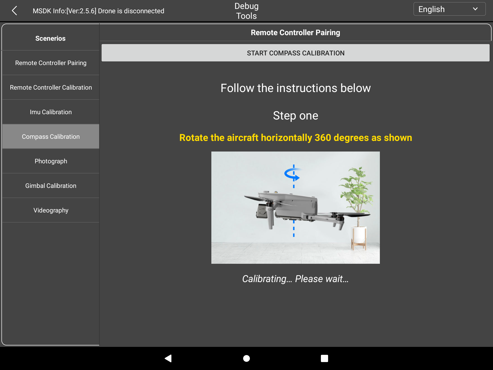
Compass Calibration: Click START COMPASS CALIBRATION and follow the instructions to calibrate the compass.
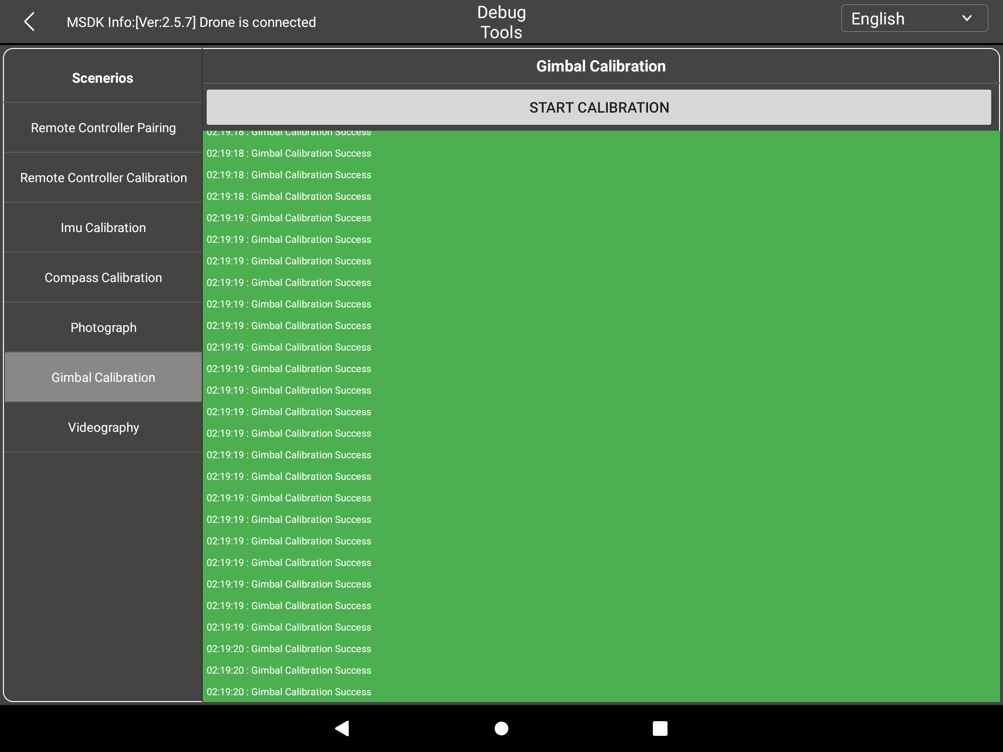
Gimbal Calibration: Click START CALIBRATION to start the gimbal calibration. When the green "Gimbal Calibration Success" appears, it means the calibration is successful.
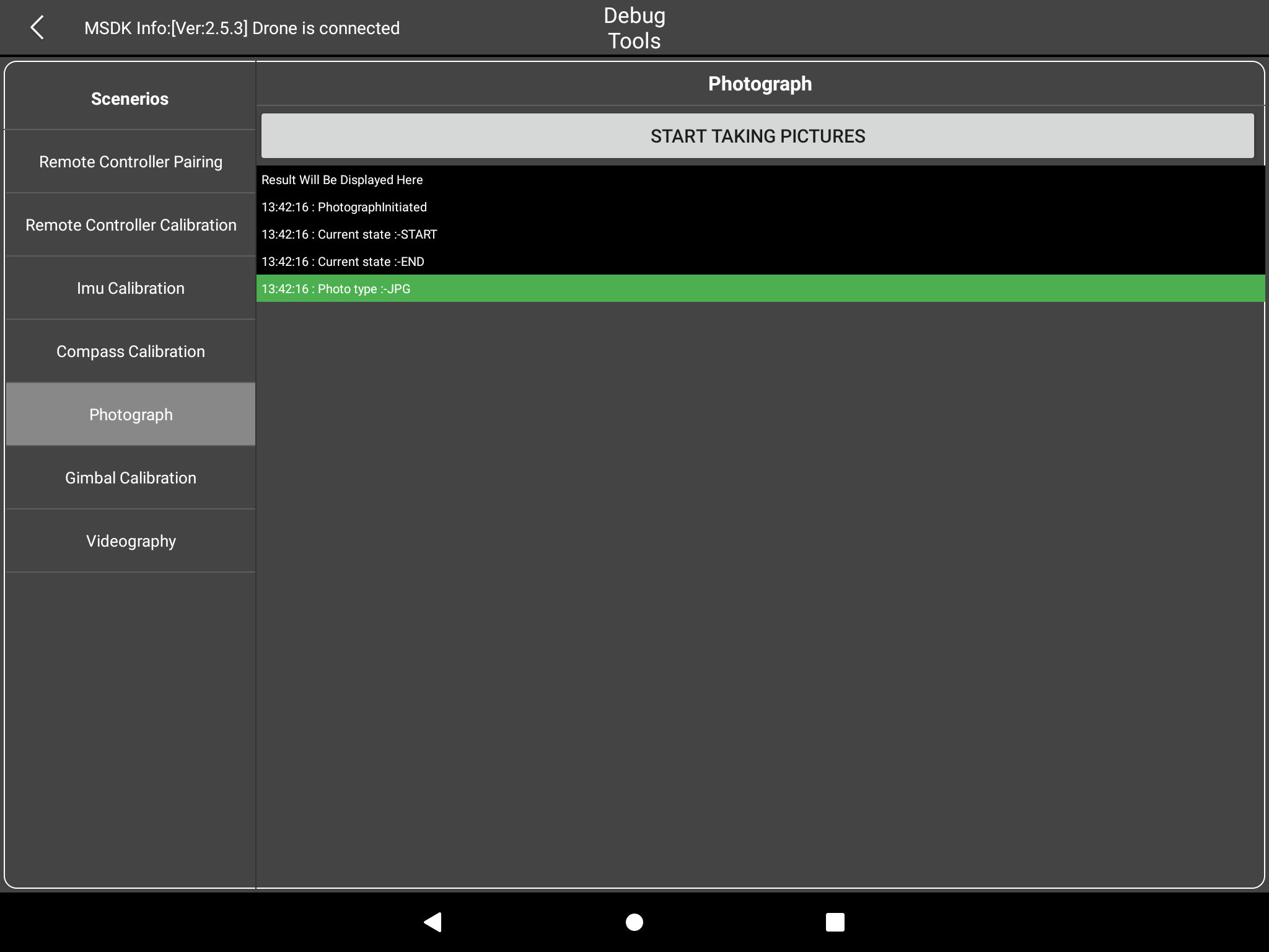
Photograph: Take photos Click START TAKING PICTURES to take photos. The results are as follows:
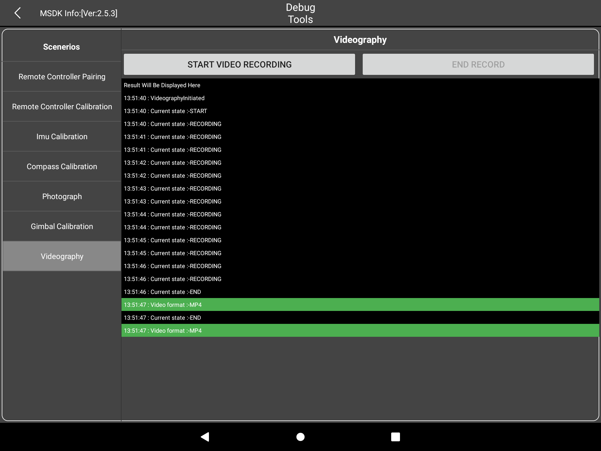
Videography: Record videos Click START VIDEO RECORDING to start recording, and click END RECORD to end recording.