UAV Hardware Interfaces
Introduction to Standard Hardware Interfaces
This document introduces the standard hardware interfaces available on the UAV and the corresponding developer kits, including pin definitions and functional descriptions. Before reading the UAV hardware connection section, ensure that you are familiar with the hardware interfaces and related accessories of the aircraft.
| UAV | Interface Name | Compatible Development Kits |
|---|---|---|
| EVO Max Series | P-Port Interface P-Port Lite Interface | PSDK Adapter Board SDK Coaxial Cable |
| Autel Alpha | P-Port Interface C-Port Interface (Can be Connected to Gimbal Adapter Ring) | Gimbal Adapter Ring PSDK Adapter Board SDK Coaxial Cable |
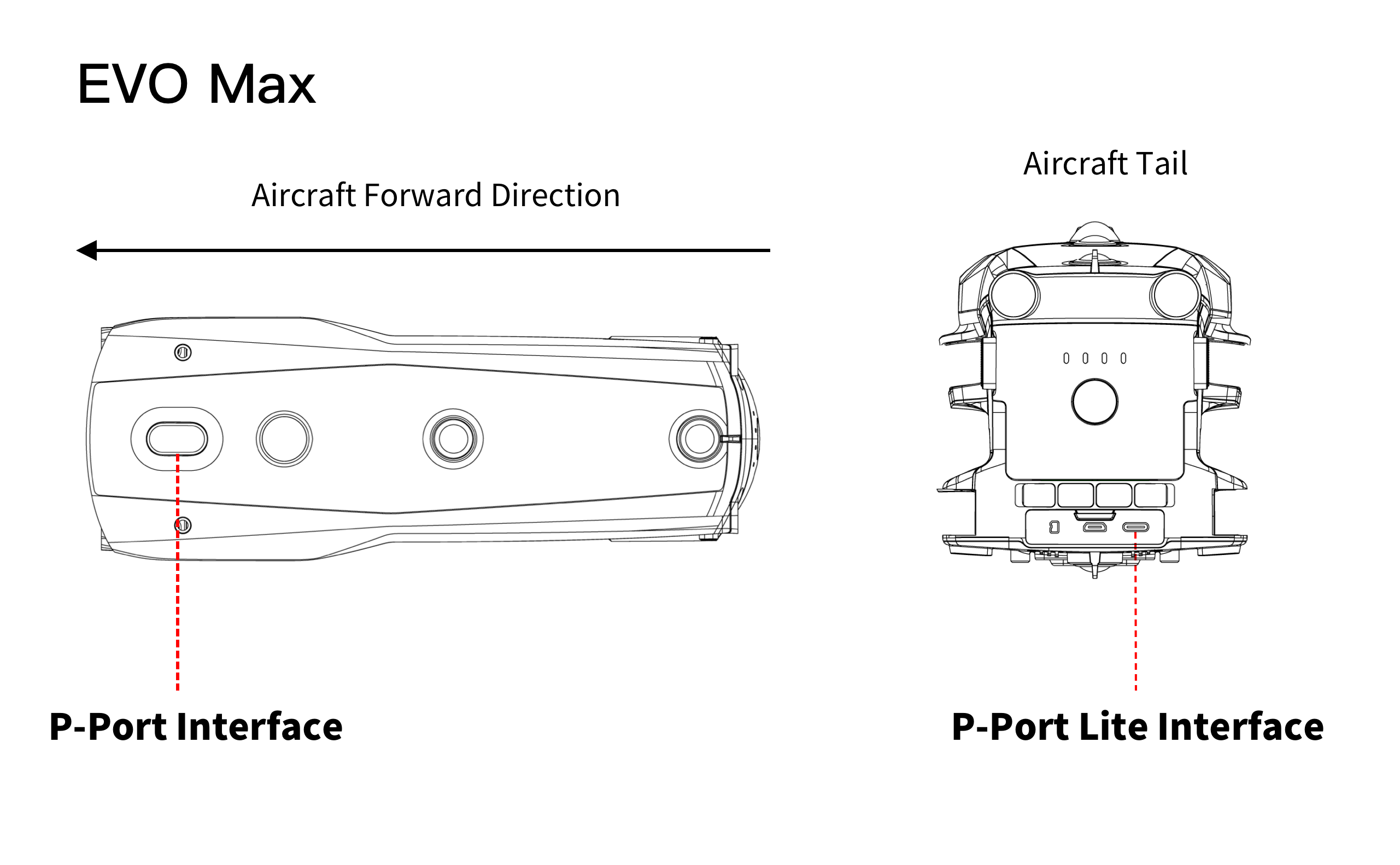
P-Port Lite Interface
The EVO Max series multirotor UAVs provide a P-Port Lite interface located at the rear of the aircraft. It adopts a USB-C physical connector, with dimensions and pin definitions consistent with the USB-C standard. It supports the USB 2.0-to-serial communication protocol and enables certain software features of the PSDK.
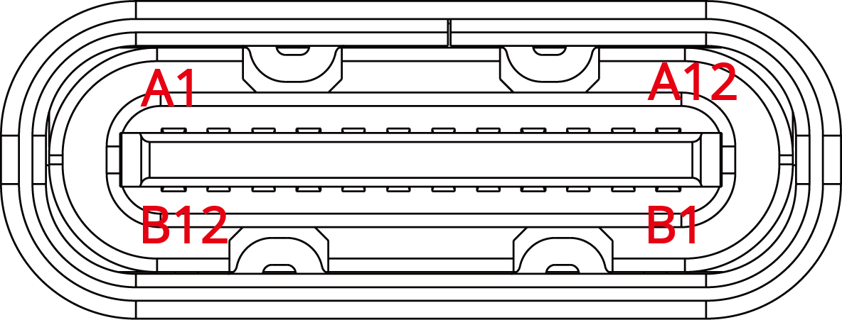
| Number | A1 | A2 | A3 | A4 | A5 | A6 | A7 | A8 | A9 | A10 | A11 | A12 |
|---|---|---|---|---|---|---|---|---|---|---|---|---|
| Interface Name | GND | TX1+ | TX1- | VBUS | CC1 | D+ | D- | SBU1 | VBUS | RX2- | RX2+ | GND |
| Number | B12 | B11 | B10 | B9 | B8 | B7 | B6 | B5 | B4 | B3 | B2 | B1 |
| Interface Name | GND | RX1+ | RX1- | VBUS | SBU2 | D- | D+ | CC2 | VBUS | TX2- | TX2+ | GND |
Notes:
- To use the P-Port Lite interface, the CC1 or CC2 pin must be pulled down to GND with a 5.1 kΩ resistor on the payload device side. This enables the VBUS to output 5 V with a current limit of 500 mA.
- The SBU1 and SBU2 pins must be connected to GND on the payload device side. To enable high-power output through the P-Port Lite interface, the VBUS voltage should be raised to between 12.8 V and 17 V, and the current increased to 3 A via the high-power request interface of the power management module.
- When using PSDK, only the VBUS, GND, D+, D-, CC1, CC2, SBU1, and SBU2 (for high-power requests) signals are required. Make sure all unused pins remain unconnected.
- When using this interface, ensure the connector is properly fixed to avoid connection issues due to vibrations from the aircraft.
P-Port Lite USB-to-Serial Chip Model Standard
| Chip Model | Compatibility |
|---|---|
| FT232 | Compatible |
| CP2102 | Compatible |
P-Port Interface
The EVO Max series multirotor UAVs provide an open P-Port interface. The interface and pin definitions are introduced as follows:
| Number | A1 | A2 | A3 | A4 | A5 | A6 | A7 | A8 | A9 | A10 | A11 | A12 |
|---|---|---|---|---|---|---|---|---|---|---|---|---|
| Interface Name | GND | NC | NC | VCC | SYNC_PPS | NC | NC | ON_DET | VCC | NC | NC | GND |
| Number | B12 | B11 | B10 | B9 | B8 | B7 | B6 | B5 | B4 | B3 | B2 | B1 |
| Interface Name | GND | NC | NC | VCC | UART_RX | USB_DM | USB_DP | UART_TX | VCC | NC | NC | GND |
Notes:
- VCC supply voltage may vary between models, so compatibility should be taken into account in the design.
- The NC pin is a reserved signal pin on the UAV side. To prevent damage to the UAV's SDK interface during development or use with third-party devices, leave the NC pin unconnected and avoid linking it to any custom interfaces on the device side.
Power Interface
- The VCC pin of the EVO Max series is rated at 12.8–17 V, with a current limit of 4 A, and total output power ranging from 51.2–68 W.
- Within the same power network, you may connect multiple VCC pins according to your actual power needs. To ensure the UAV can deliver a stable, continuous current output, it is recommended to connect all 4 VCC pins.
- The ON_DET pin (A8) is used to detect external PSDK payload devices. The other side of the ON_DET pin must be connected to GND, and no resistors should be connected in series. Only under this condition will the rated voltage be output.
Data Communication Interface
- To use USB 2.0 (USB bulk transfer, with support for future OTA upgrades) or RNDIS (TCP/IP over USB), use the USB_DP pin (B6) and USB_DM pin (B7). Note that the UAV functions as a USB Host, and the payload device must operate as a USB Device.
- To establish serial communication between the payload device and the UAV, use the UART_RX pin (B8) and the UART_TX pin (B5). Connect the UART_RX pin (B8) to the TX of the PSDK payload device, and the UART_TX pin (B5) to the RX of the PSDK payload device.
C-Port Interface
The UAV's C-Port is exclusively compatible with AUTEL Robotics official gimbals. The pin definitions of this interface are currently not disclosed. However, secondary development is supported via the gimbal adapter ring. The interface definition of the gimbal adapter ring is as follows:
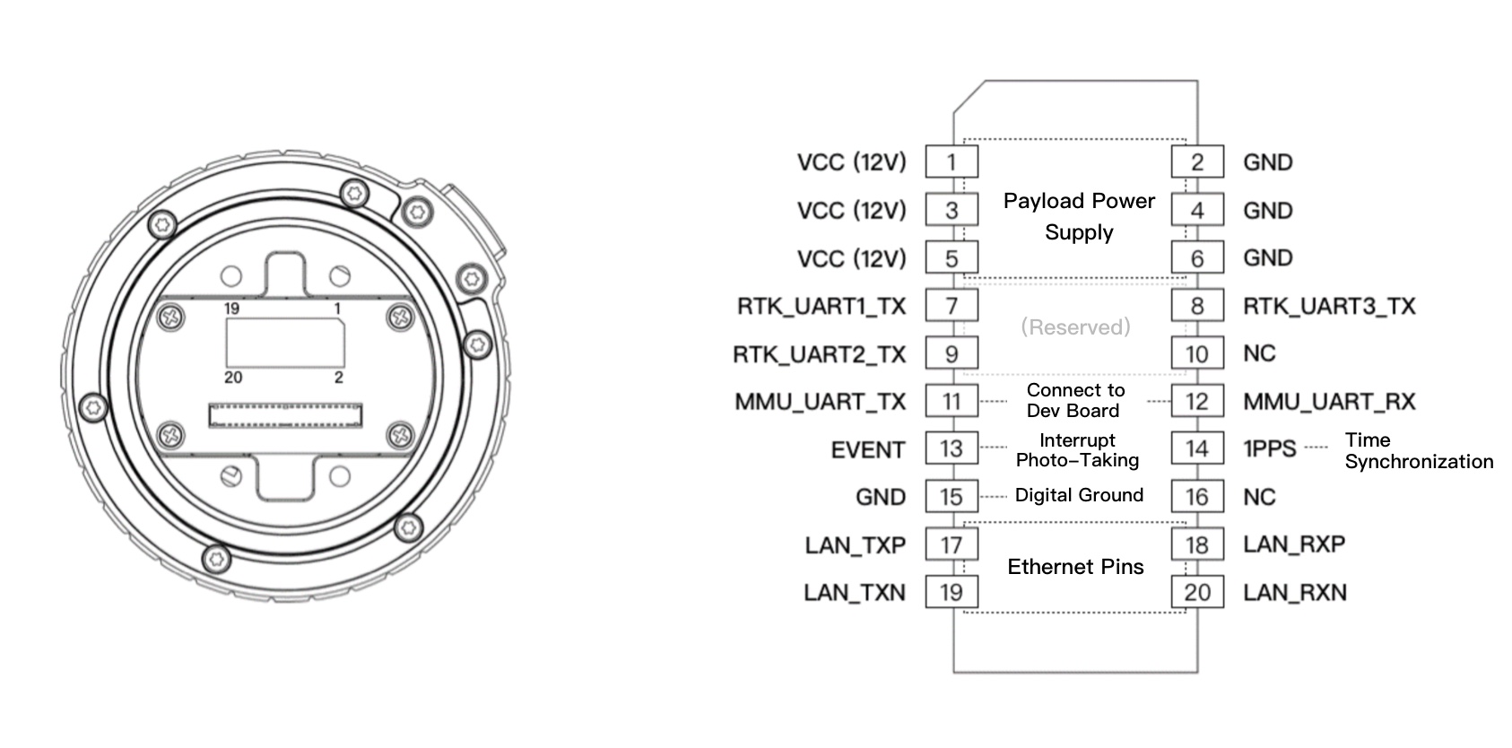
Port1
- To use the power supply function of the gimbal adapter ring, connect pins 1 through 6.
- To enable communication between payload devices developed via the gimbal adapter ring and AUTEL Robotics UAVs, pins 11 and 12 must be connected.
- To use the time synchronization feature of the PSDK, the PPS pin (14) must be connected to synchronize time with UAVs equipped with RTK functionality. The gimbal adapter ring also provides direct access to raw RTK output signals from the UAV: RTK_TX1 (pin 7), RTK_TX2 (pin 9), and RTK_TX3 (pin 8).
- To use high-speed data transmission over Ethernet, connect pins 17 through 20.
Port2
- To use the power supply function of the gimbal adapter ring, connect pins 1 through 17.
- To enable communication between payload devices developed via the gimbal adapter ring and AUTEL Robotics UAVs, pins 37 and 39 must be connected.
- To use the time synchronization feature of the PSDK, the PPS pin (19) must be connected to synchronize time with UAVs equipped with RTK functionality. The gimbal adapter ring also provides direct access to raw RTK output signals from the UAV: RTK_TX1 (pin 33), RTK_TX2 (pin 35), and RTK_TX3 (pin 34).
- To use high-speed data transmission over Ethernet, connect pins 23, 25, 29, and 31.
Payload Installation Instruction
- Remove the two screws on the cover plate and take off the upper cover;
- Remove the two screws on the quick-release plate;
- Install the adapter ring: Connect the cables properly and align the positioning structure. Then secure the payload device using four M2 × 6 screws. The threaded holes on the payload device must have a depth of no less than 5 mm;
- After completing the above steps, reinstall the quick-release plate and the upper cover;
Payload Software Development Kit (PSDK)
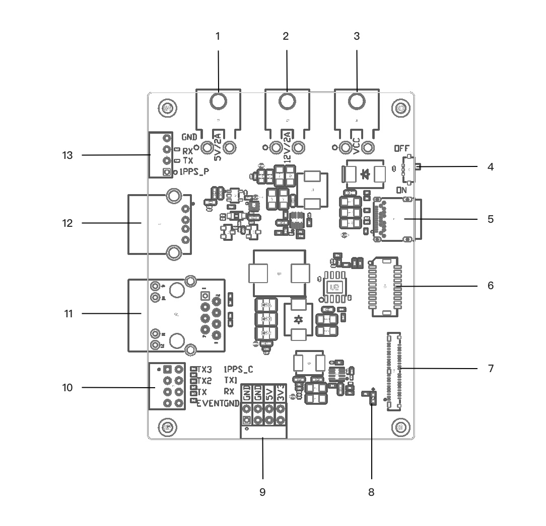
| Serial Number | P-Port Interface | Function |
|---|---|---|
| 1 | XT30 Power Output Port (5 V) | 5 V / 2 A Output |
| 2 | XT30 Power Output Port (12 V) | 12 V / 2 A Output |
| 3 | XT30 Power Output Port (VCC) | Same output power as the VCC pin of the UAV's P-Port interface |
| 4 | P-Port DIP Switch | Power control switch for the P-Port interface. When switched OFF, external voltage output is disabled. |
| 5 | P-Port / Lite Connector | Connects to the UAV’s P-Port interface or P-Port Lite interface (for EVO Max) via a corresponding coaxial cable. |
| 6 | Gimbal Adapter Ring Terminal Input | Connects to the UAV's gimbal adapter ring via terminal cable |
| 7 | Coaxial Input for Gimbal Adapter Ring | Connects to the UAV's gimbal adapter ring via coaxial cable |
| 8 | Power Indicator LED | When the P-Port DIP switch is set to ON and the system is connected to either the P-Port Lite interface or the gimbal adapter ring, the LED will light up. |
| 9 | Pin Header Power Output | Two 5 V outputs and two 3.3 V outputs |
| 10 | Adapter Ring Pin Header Signals | Pins routed from the adapter ring after connecting to the development board. TX, RX, TX1, TX2, TX3, and GND are UART pins. 1PPS_C: Can be connected to onboard device GPIOs as needed to enable the time synchronization feature. EVENT: Trigger pin for onboard device events |
| 11 | Ethernet Port | When the development board is connected to the adapter ring, onboard devices can communicate with the UAV via the Ethernet port |
| 12 | Type-A Port | USB 2.0 interface for connecting to the USB port of the payload device |
| 13 | P-Port Pin Header Signals | Pins routed from the UAV's P-Port after connecting to the development board. TX, RX, and GND are UART pins, corresponding to RX, TX, and GND on the payload device side |
Coaxial Cable

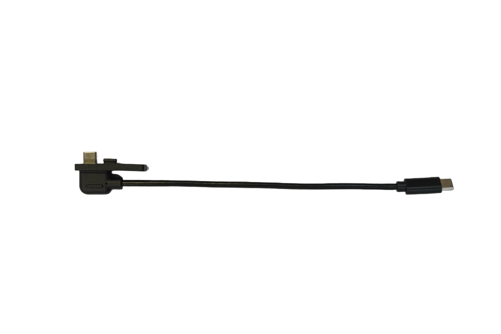
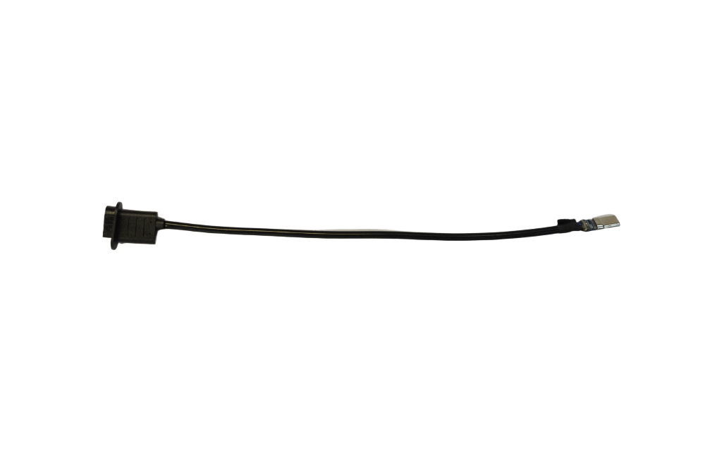
Note
- When connecting the P-port_Alpha coaxial cable or the EVO Max P-port coaxial cable to the PSDK development board, make sure the B side of the cable is facing up to ensure correct A/B side alignment
UAV Interface Description
EVO Max Series
Autel Alpha Series
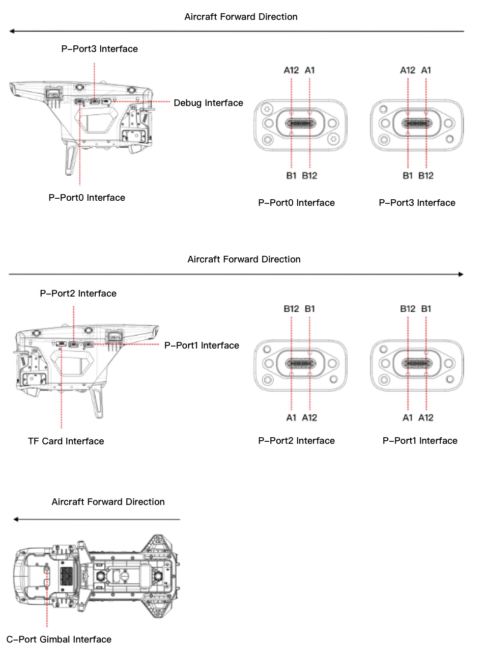
Notes:
- In some production batches of Autel Alpha, P-Port3 is labeled as OSDK. Both refer to the same hardware interface
- The P-Port2 and P-Port3 interfaces on the Autel Alpha cannot be used with USB simultaneously
- The Autel Alpha P-Port3 does not support hardware UART communication