Aircraft Hardware Interfaces
Introduction to Standard Hardware Interfaces
We introduce the standard hardware interfaces exposed by the aircraft and the associated developer kits, providing pin definitions and functional descriptions. Please read the aircraft hardware connection section after becoming familiar with the hardware interfaces and associated accessories of the model.
| Aircraft | Interface Name |
|---|---|
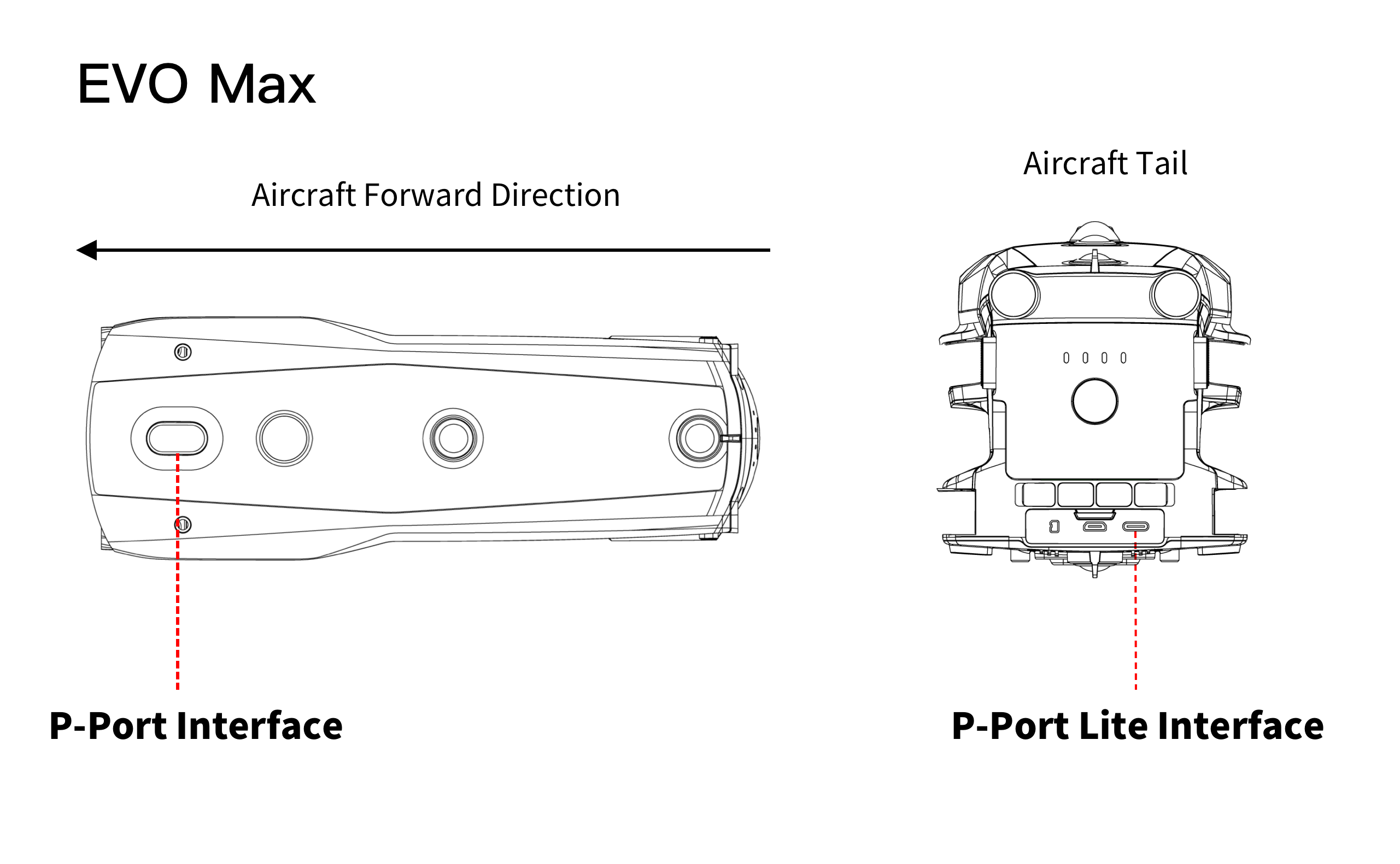
| EVO Max Series | P-Port Interface P-Port Lite Interface |
P-Port Lite Interface
The EVO Max series multirotor aircraft opens the P-Port Lite interface, located at the rear of the aircraft. It uses a USB-C physical interface, with the interface size and pin definitions consistent with the USB-C standard. It supports communication via the USB 2.0 to serial port protocol and supports some software functions of the PSDK.
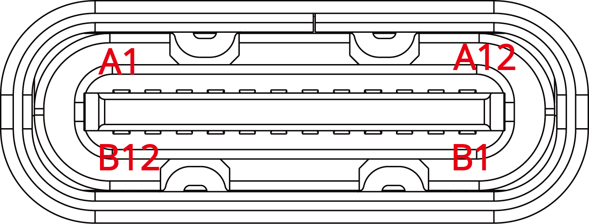
| Number | A1 | A2 | A3 | A4 | A5 | A6 | A7 | A8 | A9 | A10 | A11 | A12 |
|---|---|---|---|---|---|---|---|---|---|---|---|---|
| Interface Name | GND | TX1+ | TX1- | VBUS | CC1 | D+ | D- | SBU1 | VBUS | RX2- | RX2+ | GND |
| Number | B12 | B11 | B10 | B9 | B8 | B7 | B6 | B5 | B4 | B3 | B2 | B1 |
| Interface Name | GND | RX1+ | RX1- | VBUS | SBU2 | D- | D+ | CC2 | VBUS | TX2- | TX2+ | GND |
Note:
- To use the P-Port Lite interface, the CC1 or CC2 pin must be pulled down to GND with a 5.1K resistor on the payload device side. This will allow the VBUS to output 5V (current limit 1A).
- The SBU1 and SBU2 pins must be connected to GND on the payload device side. If high-power power supply through the P-Port Lite interface is needed, the VBUS voltage should be raised to 12.8 - 17V, and current should be increased to 3A through the high-power request interface of the power management module.
- When using PSDK, only the VBUS, GND, D+, D-, CC1, CC2, SBU1, and SBU2 (for high-power request) signals are required. Ensure that unused pins are left unconnected.
- When using this interface, ensure the connector is properly fixed to avoid connection issues due to vibrations from the aircraft.
P-Port Lite USB-to-Serial Chip Model Standard
| Chip Model | Compatibility |
|---|---|
| FT232 | Compatible |
| CP2102 | Compatible |
P-Port Interface
The EVO Max series multirotor aircraft provide an open P-Port interface. The interface and pin definitions are introduced as follows:
| Number | A1 | A2 | A3 | A4 | A5 | A6 | A7 | A8 | A9 | A10 | A11 | A12 |
|---|---|---|---|---|---|---|---|---|---|---|---|---|
| Interface Name | GND | NC | NC | VCC | SYNC_PPS | NC | NC | ON_DET | VCC | NC | NC | GND |
| Number | B12 | B11 | B10 | B9 | B8 | B7 | B6 | B5 | B4 | B3 | B2 | B1 |
| Interface Name | GND | NC | NC | VCC | UART_RX | USB_DM | USB_DP | UART_TX | VCC | NC | NC | GND |
Note:
- There are voltage differences in VCC power supply between different models, so compatibility should be considered in the design.
- The NC pin is a reserved signal pin on the aircraft side. To avoid damaging the aircraft's SDK interface during development or usage with third-party devices, leave the NC pin unconnected and do not connect it to custom interfaces on the device side.
Power Interface
- The VCC pin of the EVO Max series is rated at 12.8 - 17V, with a current limit of 4A, and total output power ranging from 51.2 - 68W.
- On the same network, you can connect multiple VCC pins based on your actual power needs. To ensure the aircraft can continuously and stably output current, it is recommended to connect all 4 VCC pins.
- The ON_DET pin (A8) is for detecting external PSDK load devices. The other side of the ON_DET pin (A8) must be connected to GND. Do not connect any resistors in series, as only then will the rated voltage output.
Data Communication Interface
- To use USB 2.0 (usb bulk transfer, with future OTA upgrade support) or RNDIS (TCP/IP over USB), use the USB_DP pin (B6) and USB_DM pin (B7). Note that the aircraft acts as a USB Host, and the load device must be a USB Device.
- To enable serial communication between the user load device and the aircraft, use the UART_RX pin (B8) and UART_TX pin (B5). The UART_RX pin (B8) should be connected to the TX of the PSDK load device, and the UART_TX pin (B5) should be connected to the RX of the PSDK load device.
Drone Interface Description
EVO Max Series